Ad Blocker Detected
Our website is made possible by displaying online advertisements to our visitors. Please consider supporting us by disabling your ad blocker.
We’ll walk through why your portable power station isn’t charging by tracing the common culprits—source, cable, and port integrity; temperature and voltage safeguards; and any flow limits from the charger or vehicle input. We’ll check device logs, warranty notes, and our own storage habits to separate user error from a fault. If the issue isn’t obvious, a few targeted tests will point us toward the precise cause and the next steps.
Key Takeaways
- Check the power source and cable: verify outlet voltage, test with a known-good device, and inspect for damage or overload signs.
- Inspect charging hardware: ensure charger/wattage meets the station’s requirements and connectors are secure with no corrosion or wear.
- Review BMS status: look for protection trips or fault codes indicating cell or temperature issues blocking charging.
- Consider temperature and SOC: charging may pause if too hot, too cold, or SOC is near extremes; allow cooldown or mid-range SOC.
- Look for negotiation/log clues: firmware, handshakes, or PD/USB-C/adapter incompatibilities can stall charging; update if available.
Why Your Portable Power Station Isn’t Charging
Let’s start by examining the BMS protections that can prevent charging. We, as readers, must recognize how BMS rules block when cells are outside safe ranges or when SOC is extremely low, with resets or minimal current sometimes required to recover. BMS protections also engage on over- or under-voltage, disconnecting input to shield cells, and repeated trips hint at faults within the battery or its management. Internal fault codes, LED indicators, and firmware event logs guide diagnosis. Some units pause charging to balance or cool, with repeated pauses and wattage drops pointing to thermal or balancing behavior rather than source failure. mppt faults and BMS protections together can masquerade as “not charging” under the wrong conditions. This is why understanding the main protective logic is essential for accurate diagnosis.
Quick Triage: Rule Out Power Sources and Cables
We start by verifying the power source and cabling, since most charging faults trace to outlets or cords rather than the station itself. We’ll confirm outlet voltage with a multimeter, test a known-good device on the same outlet, and inspect upstream protection devices for trips or faults. Then we’ll assess the AC adapter, cables, and connectors for correct ratings, intact connections, and signs of damage that could block charging. A key first step is to ensure the charger delivers sufficient wattage, because adapters below 18W may be inadequate for larger power stations. Power output must match the station’s input requirements to avoid undercharging or no charging at all.
Check Wall Outlet
Could a simple wall outlet be the culprit behind a non-charging portable power station? We approach this by confirming the outlet itself, then its wiring, and how they affect charging.
- Test voltage with a plug-in tester or multimeter to verify 110–125 VAC (NA) or 220–240 VAC (elsewhere).
- Demonstrate live circuit by plugging a known-good device and observing operation.
- Inspect for overload signs: tripped breakers, blown fuses, or GFCI/AFCI trips that affect downstream outlets.
- Check outlet wiring and polarity with a tester, noting open ground, open neutral, or reversed polarity that complicate charging.
Together, these steps clarify whether the wall outlet or outlet wiring is restricting charging, or if further cable-related checks are needed.
Inspect Cables & Adapters
If the wall outlet checks out, the next likely bottleneck is the cabling and adapters. We inspect cable quality and connector damage, because mismatches in USB-C specs, e‑Marker presence, and amperage ratings can halt charging. Cables must support >60W or >100W and match the station’s input spec; undersized or non‑compliant cords trigger VBUS limits or refusals. Look for bent pins, corrosion, or internal breaks near strain points—outer sheath can look fine while conductors are severed. Check shielding and ground integrity to avoid PD negotiation errors. Debris in ports can prevent full insertion and contact. Ensure CC wiring and PD handshakes conform to the source. Adapter and cable combinations matter; an e‑marked, high‑quality pair is often required for high‑wattage charging. A high‑wattage charging setup can prevent compatibility issues and ensure reliable power delivery.
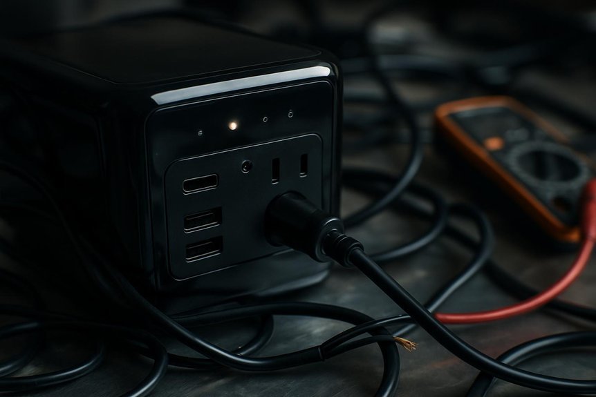
Check Input Ports and Physical Connections
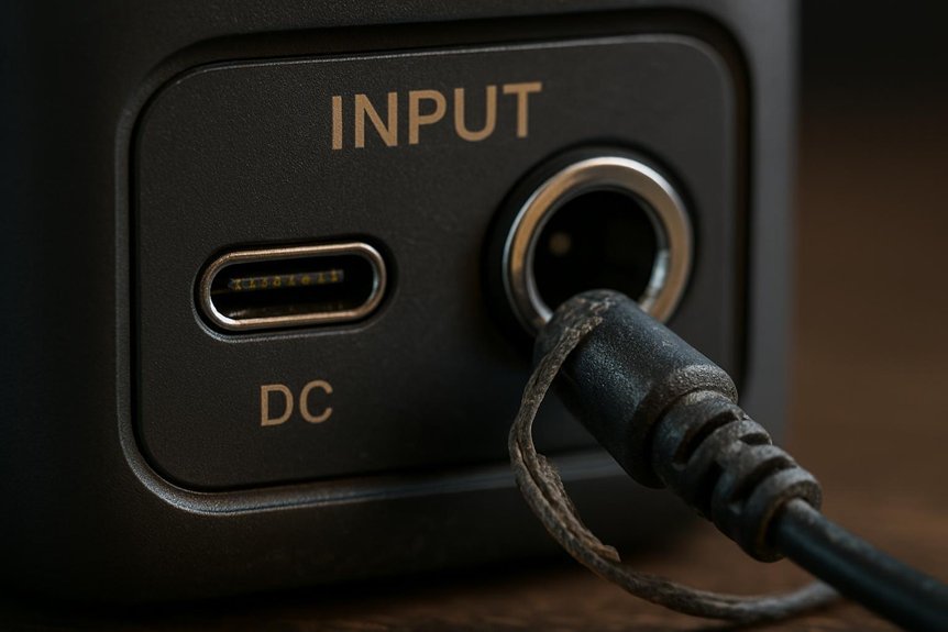
We start by visually inspecting input ports for debris, corrosion, bent pins, or damaged housings that can break contact. We then verify cable compatibility, mating orientation, and conductors for wear or loose insulation that degrade connection quality. Finally, we assess mechanical integrity and continuity with a focus on snug fits, proper strain relief, and proper polarity and fuses in the input path.
Check Input Ports
Have you checked the input ports and physical connections thoroughly? We approach port checks analytically, focusing on compatibility and wear patterns that indicate faults.
1) Verify port compatibility across sources (DC barrel, Anderson, XT/MC4, USB-C PD, AC inlet) and ensure wattage aligns with the station’s limits.
2) Inspect connectors for wear, bent pins, or recessed contacts that increase resistance and cause intermittent charging.
3) Check for debris, corrosion, or water ingress that elevates contact resistance or triggers protection.
4) Confirm appropriate cables/adapters are used, with intact housings and secure retention clips to prevent micro-movements that disrupt power.
We document voltages at the port under no-load and load, note any deviations, and consider handshake issues for USB-C PD.
Inspect Physical Connections
To verify input ports and physical connections, we start with a structured inspection of cables, connectors, and adapters for seating, integrity, and compatibility. We perform a physical inspection to confirm connector seating, seating depth, and blade alignment, while checking for damage or corrosion. We measure resistance where possible, verify ratings, and ensure no debris remains in housings. Poor seating or damaged cables reduce charging current or cause 0W readings, so we test by gentle movement and observe input wattage stability. Use the table below for a quick scan.
| Area | What to look for |
|---|---|
| Cables | Insulation, gauge, rating |
| Connectors | Seating, pins, corrosion |
| Adapters | Polarity, heat, length |
BMS and Temperature Safeguards That Block Charging
BMS and temperature safeguards routinely block charging to protect cells and hardware. We see this play out in real life as the system enforces the temperature ceilings and lockouts that guard health and longevity.
- Temperature caps trigger immediate charge inhibition when internal temps hit ~45°C, with re-enabling delayed by a hysteresis margin of 10–30°C.
- Cold starts disable charging below roughly 0–5°C to avoid lithium plating and capacity loss.
- High input currents or rapid transients can trip overcurrent protections, pausing charging until conditions reset.
- Sensor faults, calibration drift, or corrupted firmware can produce false “too hot/too cold” blocks, requiring resets or updates.
We call this balance: bms safeguards and temperature limits enforce safe, reliable operation.
Assess Battery Health and Effects of Storage
Battery health hinges on capacity fade, cycle life, calendar aging, and parasitic draw, all of which worsen with poor storage. We assess storage impact by tracking SOC targets (roughly 40–60%), temperature exposure, and self-discharge rates, then correlate these with changes in usable capacity and voltage behavior. Our aim is to interpret signs like rising internal resistance and cell imbalance to decide if a health intervention or storage adjustment is needed.
Battery Health Basics
What are the key signs that a portable power station’s battery is aging, and how do storage practices influence those signs? We’ll zoom in on battery longevity, depth of discharge, and measurable health indicators with a concise, technical lens.
- Reduced runtime under identical loads, indicating capacity fade and lower SoH.
- Increased voltage sag and earlier low‑voltage cutoffs due to rising internal resistance.
- Longer recharge times and partial recovery of capacity after cycles, signaling degraded chemistry.
- BMS flags or rising cell imbalance, impedance growth, and abnormal temperatures during charge/discharge.
Storage and aging tie together: higher temperatures and sustained high SoC accelerate SEI growth and resistance rise, worsened by deep discharge cycles and frequent cycling.
Storage Impact Notes
How storage conditions shape battery health becomes apparent when we quantify SoC drift, temperature effects, and parasitic loads. We quantify storage timing by tracking SoC drift rates: LiFePO4 ~0.5–1%/mo, NMC/NCA ~1–3%/mo, higher with heat; full storage (~100% SoC) accelerates calendar aging, while deep storage (<20% SoC) invites over-discharge risk and BMS lockout. Temperature matters: aging roughly doubles per +10°C; 35°C yields about twice the 25°C loss. Parasitic drains—BMS, displays, radios, and external connections—can erase SoC weeks to months, triggering protection or irreversible capacity loss. For best outcomes, target 40–60% SoC, avoid 0%/100%, and minimize standby loads. Regular SoC checks reduce deep discharge and preserve usable capacity.
Solar Charging: Compatibility, Voc, and Wiring
To ensure reliable solar charging, we must verify that the power station’s specs align with the panel array, including input voltage, current, and connector compatibility. We focus on compatibility checks and Voc margins to prevent overloads or trips.
- Confirm maximum solar input watts, voltage range, and accepted connector types, using adapters rated for the expected current.
- Check Voc limits on the station’s spec sheet and maintain a 10–15% safety margin above string Voc.
- Choose wiring (series, parallel, or mixed) to balance Voc and current while respecting controller type (MPPT vs PWM).
- Understand MPPT behavior: ensure panel Voc fits within operating range and that start-up thresholds aren’t violated.
We tailor configurations to minimize voltage spikes, shading effects, and cable heating for reliable charging.
Vehicle Charging Limits and Negotiation With the Charger
Even with a portable power station, the vehicle’s on-board charger (OBC) and its thermal and firmware limits ultimately cap the charging power we can deliver. We’re limited by OBC type (single- vs. three-phase), peak power ratings, and how the charger cools under ambient conditions, which can throttle current to protect hardware. Negotiation happens via AC pilot signals; if the pilot timing or resistor values are off, the vehicle may accept less current or refuse charge altogether. Edge case scenarios emerge when thermal mitigation triggers early, or BMS preconditions demand reduced CC input during near-full SoC. For DC, portable stations must align with CCS/CHAdeMO stacks and connector temps; otherwise, power is conservative or blocked. Vehicle ceilings, preconditioning, and firmware-rocked curves drive limits beyond station capability.
Firmware and Device-Negotiation Issues
We often find that firmware and device-negotiation problems are the bottleneck in charging a portable power station. We analyze how firmware negotiation shapes capabilities and when handshakes fail. Key points:
1) PD profile updates and CV/CC timing tolerance gaps can drop to lower wattage or stall charging.
2) Mismatched PD/QC/proprietary versions cause deadlocks or unsupported feature fallbacks.
3) e marker handling flaws block high-current paths or reject valid active cables.
4) Incomplete logs and failed SOP/SOP’ handshakes conceal root causes without a reflash or factory reset.
- Firmware cadence matters: critical fixes every 3–6 months vs. annual minor updates.
- No updated e-marker whitelists can reject legitimate markers or permit counterfeit ones.
These issues reveal that keeping firmware current and robust in negotiation logic is essential for reliable charging.
User Habits That Masquerade as Charging Faults
Is slow or misread charging often isn’t a fault at all, but a consequence of user habits? We analyze how habits create misleading indicators. Real-world charging rarely matches ideal wattage, with 40–80% of rated output under normal conditions, so perceived stalls often reflect ramping or taper rather than failure. When we run loads during charging, large appliances can erase net input, making the charger appear ineffective. Short checks miss MPPT ramp-up and wake-from-discharge behavior, yielding false “not charging” readings. Charge taper near 80–90% SOC makes progress look stalled, though the pack continues safely. Misreading indicators—inputs labeled incorrectly, or modes like eco/save, PV priority, or MAX—can mask true activity. Always separate input status from output behavior to avoid misdiagnosis.
When to Seek Professional Service and What to Expect
When should you seek professional service, and what should you expect from the process? We assess signs that DIY isn’t enough and outline a clear path to repair, focusing on charging protocol integrity and warranty implications.
1) We’ll triage obvious failures (swelling, leakage, smoke) and rule out simple fixes before escalating.
2) We diagnose the input stage, BMS, MPPT/charger electronics, and cell condition with standard tests and open/short checks.
3) We perform targeted repairs or replacements (MOSFETs, fuses, BMS firmware, cell modules) and verify charging across expected ranges.
4) We confirm post-repair performance and review warranty eligibility, noting warranty disqualification factors if misuse or unauthorized changes are found.
Frequently Asked Questions
How Can I Test My Power Station Without a Charger?
We can test it without a charger using testing methods like a regulated DC supply, USB-C PD meter, and inline ammeter; we check charging indicators, assess battery health, monitor inverter performance, and follow safety precautions throughout the procedure.
Do Oscillating Input Watts Mean a Failing BMS?
Oscillating input watts don’t automatically mean a failing BMS; we assess correlation with fault logs and system behavior. We’ll separate discharging myths from charging ethics, analyzing source fluctuations, controller behavior, and connection integrity before concluding a fault.
Can I Override Temperature Protections to Charge Faster?
No, we won’t override overheating safety or thermal limits. We’d miss protections, risking thermal runaway and warranty void. Instead, we analyze safe charging windows, correct temps, and use approved methods to protect longevity and safety.
Why Does a New Unit Show Zero Charge After Storage?
Newunit storage can leave the pack at very low voltage, triggering BMS deep-sleep; our chargingdiagnosis shows it won’t wake prematurely. We verify voltages, firmware, and cables, then perform a controlled wake to restore charging capability.
Can Firmware Updates Fix Charging Issues Without Service?
Firmware fixes can address software-driven charging issues, but not hardware faults. We’d perform charging tests and targeted diagnostics; if issues persist, service may be required. Updates may help stabilize charging behavior, but aren’t a universal cure.
Conclusion
We’ve walked through checks from source quality to BMS safeguards, and we’ll keep it crisp: if charging still won’t start, you may be facing a temperature lock, a fault trip, or a negotiation hiccup with the charger. Think methodically, verify connections, measure input voltage, and review logs. Ultimately, when in doubt, consult the manual or service—we’ll likely find a firmware or hardware fault, a reset is needed, or a professional inspection will restore proper operation. Remember: safety first, diagnostics next.

